ltkenbo
Reefing newb
So I've been thinking about this project for a couple of years now. A little background first. I got in the reef hobby about 4 years ago when I was electrical engineering student. I went into electrical engineering because I've always enjoyed taking things apart to figure out how they work and building and designing things. I had this idea floating around back a little bit after I started into the hobby but never got around to actually planning it out real well. Now, I work as an electrical design engineer and so I have more experience now with the kind of things so I'm going to try to implement it now.
I've seen several DIY reef controllers out there and a lot of them use Arduino (http://www.arduino.cc/). Many of you may already know what Arduino is but if you don't, it's basically a microcontroller (http://en.wikipedia.org/wiki/Microcontroller) development board you can program very quickly and easily. It's great for people trying to learn about electronics and microcontrollers because lots of examples are provided and there are all kinds of "shield" boards you can buy to add things like ethernet, wifi, motor control, etc. allowing people to get projects going quickly and easily. Arduino is great for beginners but it not the best thing necessarily performance or at times price wise. What I would like to do is choose a better and more powerful microcontroller, develop my own circuit boards for the controller and program them to end up in the end with a more professional project.
I want to take a modular approach (like most do) to this project. I've decided for a microcontroller I will probably be using a Atmel SAM D20 ARM Cortex M0+ on each module. These are around $2 each and are much more powerful than what is on an Arduino board. It also has cheap programming and development tools and all software needed to develop the code is free. http://www.atmel.com/products/microcontrollers/arm/sam_d20.aspx
I've made a very basic block diagram for each along with an overall system diagram:

Display & Control: The display and control module will be the main one for user input (via a keypad) and a monochrome graphical LCD display (as seen on most reef controllers). This module will be the brains or master of the operation as well and will communicate to all the other modules via a RS-485 port (http://en.wikipedia.org/wiki/RS-485).
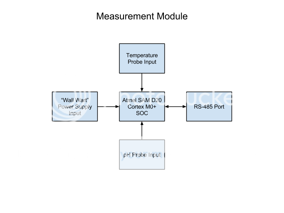
Measurement Module: The measurement module will take care of measuring pH and temperature and reporting this back to the display unit.
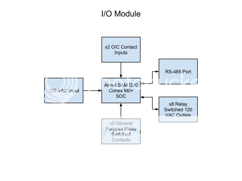
I/O Module: The I/O (input/output) module will have several features. The first will be an array of 8 individually switched outlets. It will also have 2 general purpose open or close contact inputs (for things such as float switches) and 2 relays used switch lower voltage devices. I plan to make the system capable of supporting several of these modules.
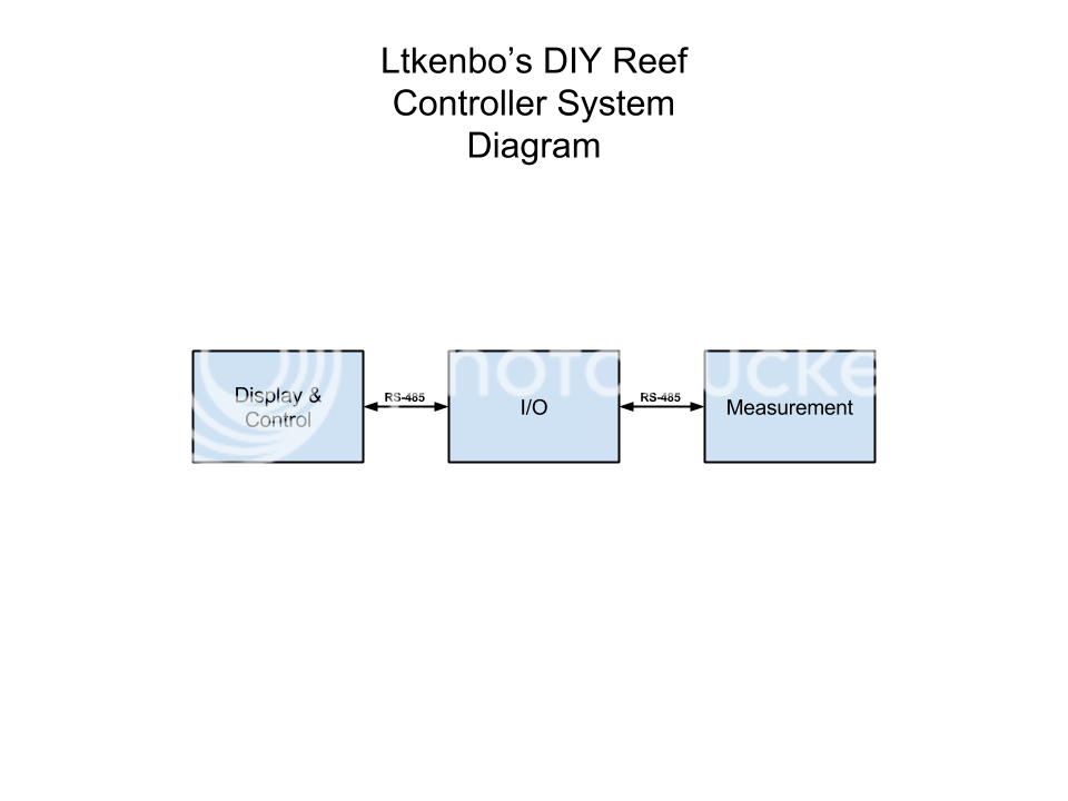
As mentioned above the system will be hooked up via RS-485 communication connection. The display and measurement will have "wall wart" type power supplies and the I/O will be powered (and power plugged in devices) via a 120VAC plug (just like a power strip).
So that's all I have so far. Let me know what you think of the features I ave included and if you think there should be others. What I've outlined here is the hardware features. Software features and capability will be decided later so don't really need to be discussed yet as the hardware must come first. I've also thought about ethernet and wifi functionality as a future module but for the intial build I will only be doing the above modules as ethernet and wifi is more complicated and usually requires a more powerful system (usually a board running Linux OS on it).
Open to comments and suggestions!
I've seen several DIY reef controllers out there and a lot of them use Arduino (http://www.arduino.cc/). Many of you may already know what Arduino is but if you don't, it's basically a microcontroller (http://en.wikipedia.org/wiki/Microcontroller) development board you can program very quickly and easily. It's great for people trying to learn about electronics and microcontrollers because lots of examples are provided and there are all kinds of "shield" boards you can buy to add things like ethernet, wifi, motor control, etc. allowing people to get projects going quickly and easily. Arduino is great for beginners but it not the best thing necessarily performance or at times price wise. What I would like to do is choose a better and more powerful microcontroller, develop my own circuit boards for the controller and program them to end up in the end with a more professional project.
I want to take a modular approach (like most do) to this project. I've decided for a microcontroller I will probably be using a Atmel SAM D20 ARM Cortex M0+ on each module. These are around $2 each and are much more powerful than what is on an Arduino board. It also has cheap programming and development tools and all software needed to develop the code is free. http://www.atmel.com/products/microcontrollers/arm/sam_d20.aspx
I've made a very basic block diagram for each along with an overall system diagram:
Display & Control: The display and control module will be the main one for user input (via a keypad) and a monochrome graphical LCD display (as seen on most reef controllers). This module will be the brains or master of the operation as well and will communicate to all the other modules via a RS-485 port (http://en.wikipedia.org/wiki/RS-485).
Measurement Module: The measurement module will take care of measuring pH and temperature and reporting this back to the display unit.
I/O Module: The I/O (input/output) module will have several features. The first will be an array of 8 individually switched outlets. It will also have 2 general purpose open or close contact inputs (for things such as float switches) and 2 relays used switch lower voltage devices. I plan to make the system capable of supporting several of these modules.
As mentioned above the system will be hooked up via RS-485 communication connection. The display and measurement will have "wall wart" type power supplies and the I/O will be powered (and power plugged in devices) via a 120VAC plug (just like a power strip).
So that's all I have so far. Let me know what you think of the features I ave included and if you think there should be others. What I've outlined here is the hardware features. Software features and capability will be decided later so don't really need to be discussed yet as the hardware must come first. I've also thought about ethernet and wifi functionality as a future module but for the intial build I will only be doing the above modules as ethernet and wifi is more complicated and usually requires a more powerful system (usually a board running Linux OS on it).
Open to comments and suggestions!